
Have you ever wondered how energy is distributed within a PCB to power various electronic components? A PCB comprises numerous miniature components, and designing a power system capable of supplying energy to each element is an intricate task. As circuit density and complexity increase, power design becomes progressively challenging. A flawless power design is essential to overcome these hurdles, requiring meticulous planning to address issues such as electromagnetic interference (EMI), component selection, current loop minimization, and trace design for high currents. Additional critical parameters include voltage regulation, current flow, and thermal management. Here’s a detailed look at the key factors in PCB power design:
1. Choosing the Right Voltage Regulator
Selecting an appropriate voltage regulator is a pivotal step in power design. Designers typically choose between linear and switching regulators:
Linear Regulators:
Linear regulators offer low-noise output but generate significant heat, necessitating thermal management solutions like heatsinks. They require the input voltage to exceed the desired output by a minimum voltage difference. Despite their simplicity and low cost, the efficiency of linear regulators is lower due to high power dissipation. Low-dropout (LDO) linear regulators are recommended to reduce thermal inefficiency, but thermal analysis is crucial before implementation.
Switching Regulators:
Switching regulators utilize inductors to temporarily store energy and release it at different voltages during switching cycles. They employ high-frequency MOSFETs for efficient energy conversion, and the output voltage is controlled via pulse-width modulation (PWM). While highly efficient with minimal heat generation, switching regulators introduce noise and ripple due to high-speed switching. EMI from these regulators can be mitigated through filtering, ground plane optimization, and shielding. Implementing electromagnetic compatibility (EMC) measures is essential before integrating switching regulators.
2. Thermal Management
Power supply performance is directly linked to effective heat dissipation. Most electronic components generate heat as current flows through them, with the dissipation varying based on power rating, impedance, and operating conditions. Managing heat requires:
- Active Cooling: Incorporating cooling mechanisms such as fans ensures consistent temperature control for systems with high heat generation.
- Heat Dissipation Aids: Use thermal vias, heat sinks, or thermal pads near high-power components to transfer heat away efficiently.
- Combining conduction-based (e.g., heat pipes, thermal vias) and convection-based (e.g., fans) cooling methods can significantly enhance power design efficiency.
3. Ground and Power Planes
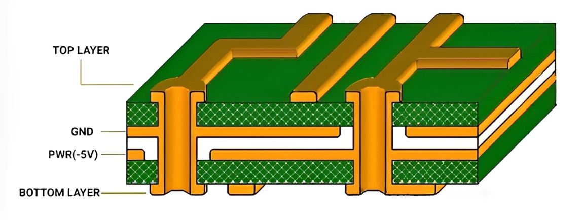
Dedicated ground and power planes provide low-impedance paths for efficient power delivery, reducing EMI, crosstalk, and voltage drops. In multilayer PCBs, assigning specific layers for ground and power enhances signal integrity and minimizes interference between circuits. Effective segregation of ground planes for analog and digital circuits further prevents noise coupling.
4. Decoupling and Bypass Capacitors
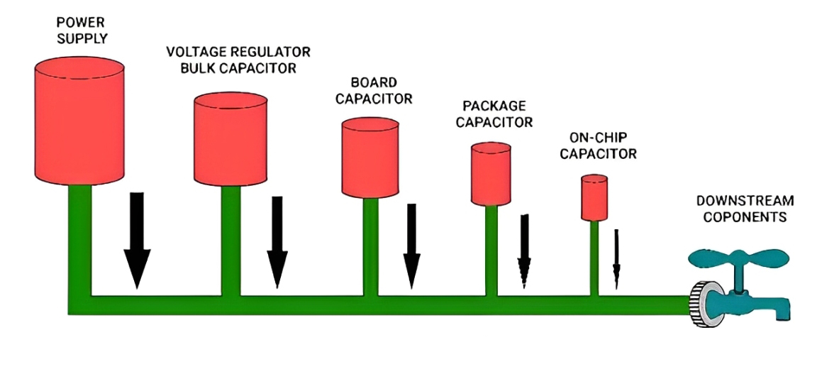
Decoupling and bypass capacitors are essential for stabilizing power delivery and suppressing noise:
- Decoupling Capacitors: Placed near IC power pins, these capacitors act as localized charge reservoirs to support transient current demands and reduce power-to-ground impedance.
- Bypass Capacitors: Positioned between power and ground pins, bypass capacitors suppress noise in power lines and stabilize voltage fluctuations caused by switching events.
To ensure optimal performance, designers should select capacitors with appropriate dielectric materials, values (typically 0.1 μF for ceramics), and placement.
5. EMI Filtering
EMI filters are used at the power supply input to suppress conducted noise and maintain electromagnetic compatibility. Proper layout of filter components minimizes parasitic coupling and ensures efficient noise suppression.
6. Load Response and Frequency Considerations
When a power supply experiences sudden load changes, the output voltage may exhibit transient drops or overshoots. Proper selection and placement of output and compensation capacitors mitigate such effects. For example, including a 0.1 μF capacitor at the output pin of an LM7805 regulator ensures stability. Separately managing AC and DC circuits prevents unwanted interactions.
7. Power Integrity (PI)
Power integrity ensures consistent power delivery across the PCB, minimizing noise and maintaining operational stability. PI design involves:
- Simulating voltage drops and hotspots.
- Strategically placing decoupling capacitors.
- Ensuring robust trace and via design to handle high currents efficiently.
- Simulation tools aid in optimizing power delivery and identifying potential bottlenecks in the design.
A well-designed power system is essential for the reliable operation of electronic devices. By addressing considerations like regulator selection, thermal management, EMI suppression, and power integrity, designers can create efficient and stable PCB power systems. Following datasheet guidelines for power ICs and optimizing trace widths and component placement are critical for successful designs. Proper planning and execution ensure the delivery of clean and consistent power, meeting the demands of modern electronic circuits.


