
1. Capacitor Failures
Capacitors are the most frequent culprits in electronic device malfunctions, particularly electrolytic capacitors. Common failure modes include reduced capacitance, complete loss of capacitance, leakage, or short circuits.
The role of a capacitor in a circuit determines the type of failure it may cause. For instance, in industrial control circuit boards dominated by digital circuits, capacitors primarily serve as power supply filters, with fewer used for signal coupling or oscillation circuits. If an electrolytic capacitor in a switching power supply fails, the circuit may stop oscillating, resulting in no voltage output. Alternatively, poor voltage filtering may occur, causing unstable voltage and logic confusion, manifesting as intermittent functionality or an inability to power on.
This issue is particularly evident in computer motherboards. After years of use, booting issues often arise, sometimes resolving temporarily. Upon inspection, one can often find bulging electrolytic capacitors. Measuring their capacitance usually reveals significant deterioration.
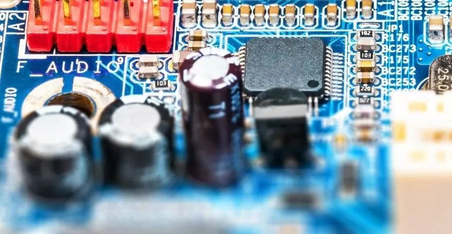
Capacitor lifespan is closely tied to environmental temperature—higher temperatures significantly shorten lifespan. This principle applies to all capacitors, not just electrolytes. Therefore, when diagnosing faults, prioritize inspecting capacitors located near heat sources like heat sinks or high-power components. The closer the capacitor is to the heat source, the more likely it is to fail.
Capacitors with significant leakage may feel hot and must be replaced. When diagnosing intermittent faults unrelated to poor connections, capacitor failure is often the cause. Replacing suspicious capacitors often yields surprising results.
2. Resistor Failures
Resistors are the most numerous components in electrical devices, yet they are not the most failure-prone. Resistor failures typically involve open circuits, with increased resistance being less common and decreased resistance being extremely rare.
Common resistor types include carbon film, metal film, wire-wound, and fuse resistors. The first two types are widely used and exhibit distinct failure characteristics:
- Low Resistance (<100Ω) and High Resistance (>100kΩ) resistors have higher failure rates, whereas mid-range values (hundreds of ohms to tens of kilohms) rarely fail.
- Low Resistance Failures are often visible as charring or blackening, making them easy to identify. Conversely, High Resistance Failures usually lack visible traces.
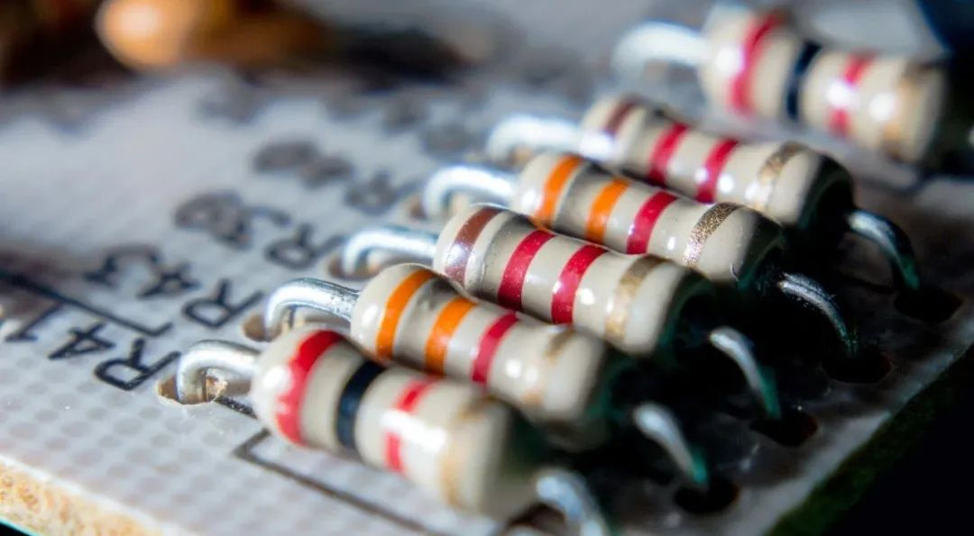
Wire-wound resistors, used for high-current applications, often show burn marks, surface cracks, or blackening when they fail. Cement resistors (a type of wire-wound resistor) may fracture when burnt, while fuse resistors may lose a piece of their surface.
To quickly identify faulty resistors, check for burn marks on low-resistance components and measure high-resistance components with a multimeter. If the measured resistance is higher than the nominal value, the resistor is faulty. Ensure stability in readings before concluding, as capacitors in parallel circuits may influence measurements.
3. Operational Amplifier Failures
Judging the condition of operational amplifiers can be challenging. Understanding their key characteristics, such as "virtual short" and "virtual open," is crucial for analyzing linear circuits.
Operational amplifiers must operate in closed-loop (negative feedback) configurations for linear applications. In open-loop (comparator) mode, their behavior changes. When diagnosing, determine whether the amplifier is used for signal amplification or as a comparator.
For amplifiers, the voltage at the non-inverting (+) and inverting (-) inputs should match closely, with any difference typically in the millivolt range. If the difference exceeds 0.5V, the amplifier is likely faulty. In comparator configurations, mismatched input voltages are permissible, and output voltages will either approach the supply voltage or ground. Voltage deviations from these norms indicate a fault, allowing diagnosis without chip replacement.
4. SMT Component Failures
Surface-mounted components (SMT) can be challenging to test due to their small size and protective coatings. A practical solution is modifying multimeter probes by attaching sewing needles with fine copper wire and soldering them. These needle-like probes can penetrate insulation layers and access component terminals, simplifying testing.
5. Common Power Supply Short Circuits
Power supply shorts are challenging to diagnose due to the numerous components sharing the same power source. If the board has a few components, systematic isolation may help. Using a current-limited adjustable power supply (e.g., 0–30V, 0–3A) is effective for densely populated boards. Gradually increase the current while monitoring for overheating components, which are often the source of the short. Ensure the voltage remains within the component's rated range to prevent further damage.
6. Board-Level Faults
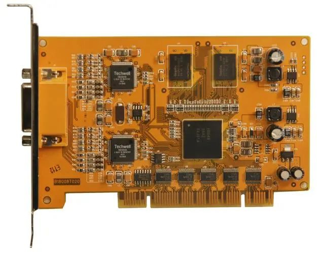
Industrial control boards, often exposed to harsh environments, are prone to contact issues. Dust, moisture, and corrosive gases can degrade contact surfaces. Cleaning the board’s connector "gold fingers" with an eraser can often restore functionality, offering a simple, cost-effective solution.
7. Electrical Faults
Intermittent electrical faults often result from:
- Poor Connections: Issues with board connectors, cables, or solder joints.
- Signal Interference: External noise disrupting digital circuits.
- Thermal Instability: Components like electrolytic capacitors degrade under heat.
- Contamination: Moisture or dust altering circuit parameters.
- Software Configuration: Parameter limits triggering false alarms under specific conditions.
Proper diagnostics and regular maintenance are essential for preventing these faults.


