Some people do PCB wiring directly without analysis, they will encounter many problems later.
For example, the power wires and miscellaneous wires are finished, but a group of important signal lines are missed, which results in this group of wires not being able to be in the same group and layer. There is not even a complete reference plane, and the previous wiring has to be modified greatly, which is time-consuming and laborious.
If the PCB is compared to our city, the components are like all kinds of buildings, and the signal wires are the streets and alleys in the city, and the appearance of each road has its detailed planning, and the wiring is also the same.
1. Wiring sequence requirements
Critical signal wires take precedence
Key signals such as power supply, simulated small signal, high-speed signal, clock signal and synchronization signal, are prioritized.
Principle of priority of wiring density
Start with the components that have the most complex connection with the board. Wiring starts at the densest area of the board.
Precautions for key signal processing
Try to provide a special wiring layer for key signals such as clock signals, high-frequency signals, and sensitive signals, and ensure their smallest loop area. If necessary, methods such as shielding and increasing safety spacing should be used. Signal quality should be guaranteed.
Impedance control
Networks with impedance control requirements should be arranged on the impedance control layer to avoid signal cross-segmentation.
2. Wiring crosstalk control
3W principle
Keep the distance between wires 3 times the wire width. In order to reduce wire crosstalk, the wire spacing should be large enough. If the wire center distance is not less than 3 times the wire width, 70% of the wire electric field can be kept from interfering with each other, which is called the 3W rule.
.png)
Crosstalk control
Crosstalk refers to the mutual interference between different nets on the PCB due to long parallel wiring, mainly due to the effect of distributed capacitance and distributed inductance between parallel wires.
Major measures to overcome crosstalk:
Increase the spacing of parallel wiring, and obey 3W rule;
Insert grounded isolation wires between parallel wires;
Decrease the distance between wiring layer and ground level
3. General requirements for wiring
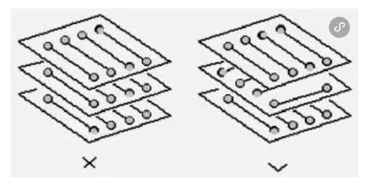
The adjacent planes wiring directions are orthogonal
Avoid different signal wires in the same direction on adjacent layers to reduce unnecessary interlayer interference; When it is difficult to avoid this situation due to the structural limitations of the board (such as some backplanes), especially when the signal rate is high, isolating each wiring layer with a ground plane and isolating each signal wire with a ground signal wire should be considered.

Small discrete device wiring must be symmetrical
SMT pad leads with dense spacing should be connected from the outside of the pad, and direct connection between the pad is not allowed.
.png)
Loop minimum rule
The loop area composed by signal wires should be as small as possible, the smaller of the loop area, the less radiation to the outside world, and the smaller the interference from the outside world.
.jpg)
No STUB
No STUB is allowed for wiring.
.png)
The same network wiring width is the same
The wiring width of the same network should be consistent, and the change of wire width will cause uneven impedance of the wire characteristics, and reflection will occur when the transmission speed is high.
Under certain conditions, such as connector lead-out, BGA package lead-out, the spacing is too small to avoid the change of wire width, and the effective length of the inconsistent part should be minimized.
(1).png)
Avoid signal wires to form loop at different layers
Signal wires may form loop at many layers board, and self loop will cause radiation interference.
.jpg)
Avoid sharp and right angles
Sharp and right angles should be avoided in PCB design, sharp and right angles can cause unnecessary radiation, and bad PCB production process performance.
.png)


